NEWS

News

ATTC Technology Sharing | New Capabilities of High Speed Single Motor Test Bench Launched
2024-04-10 13:32:33

In today's industrial and technological development, efficient motor technology has become a key factor driving innovation. Especially in the field of high-speed motors, the requirements for technology are even more stringent. Today, we will explore an important and cutting-edge topic - the high-speed single motor test bench. This article not only represents the latest progress in motor technology, but also has a profound impact on the development of the entire industrial automation and electric vehicle industry.


图片


In this article, we will focus on introducing a key equipment - a high-speed single motor test bench, which is designed specifically to meet the performance and reliability testing of new energy vehicle drive motors and motor controllers. If you are interested in efficient and reliable new energy vehicle motor technology, or want to gain a deeper understanding of advanced technologies and innovative methods in motor testing, then this article will be a valuable resource that you cannot miss.


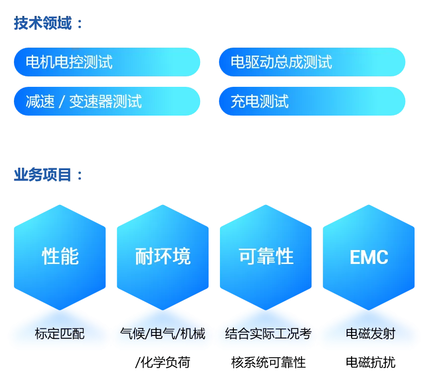
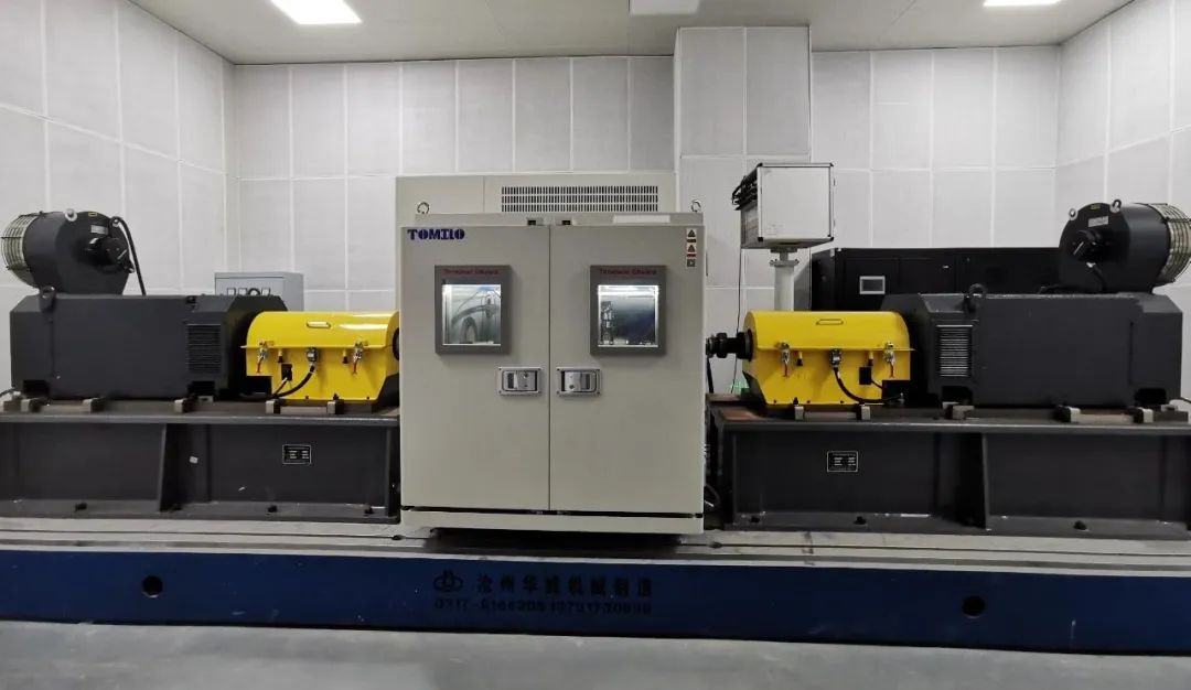
Purpose of bench test

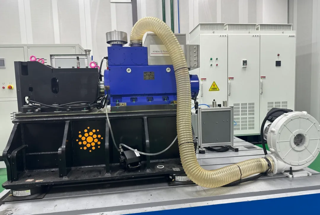
This test bench system is mainly used for the performance and reliability test of the drive motor and motor controller of new energy vehicles. It meets the technical requirements of the actual test, and has superior performances such as progressiveness technology, high accuracy, high reliability, easy maintenance, and high safety. It also meets the relevant standards of the national electric vehicle motor drive system test:

>GB/T 18488.1-2015 Electric Vehicle Drive Motor Systems Part 1: Technical Conditions

>GB/T 18488.2-2015 Electric Vehicle Drive Motor Systems Part 2: Test Methods

>GB/T 29307-2012 Reliability Test Methods for Drive Motor Systems for Electric Vehicles

>GB/T 755-2019 Rating and Performance of Rotating Electrical Machines

>GB/T 22669-2008 Test methods for three-phase permanent magnet synchronous motors

>GB/T 1032-2005 Test methods for three-phase asynchronous motors

>QC/T 1022-2015 Technical Conditions for Reducer Assembly for Pure Electric Passenger Cars

>GB/T 8196-2003 General requirements for the design and manufacture of fixed and movable protective devices for the safety of machinery

>GB/T 4793.1-2007 Safety Requirements for Electrical Equipment for Measurement, Control and Laboratory Use Part 1: General Requirements

>GB/T 50055-2011 Design Specification for Distribution of General Electric Equipment

>GB 5226.1-2008 Mechanical and Electrical Safety Mechanical and Electrical Equipment Part 1: General Technical Conditions

>ISO 13849-1-2015 Safety related components of control systems

>GB/T 16855.1-2018 Mechanical Safety Control System Safety Related Components


Bench working environment

1、 Environment

>Platform room temperature: 5 ℃~30 ℃;

>Environmental relative humidity: ≤ 95% RH;


2、 Water supply

>Cooling water: ≤ 32 ℃, pressure: 3-4 bar;

>Tap water;


3、 Compressed air

>0.6MPa~0.8MPa, industrial grade.


Main testing content

图片

图片


Overall structure of the platform

图片

↑↑↑ Platform System Diagram


Mechanical structure of the platform

The mechanical system as a whole adopts the main high-speed transmission system of Austria's Tectos company. We are the top "test bench specific" transmission system and NVH engineering consulting solution company in the industry. Our products include but are not limited to universal joints, couplings, prosthetic transmissions, intermediate bearings, docking systems, high-speed electric drive test bench transmission systems, high-speed coaxial acceleration boxes, professional transmission shaft matching and selection software, bench NVH engineering solutions, high-speed electric drive bench monitoring and protection equipment, product NVH engineering consulting and product development, etc.


图片图片

↑↑↑ Platform layout diagram


Platform accuracy indicators

>Steady state torque control accuracy: ≤ ± 0.5% FS;

>Torque measurement accuracy: ≤ ± 0.05% FS;

>Steady state speed control accuracy: ≤ ± 1rpm;

>Speed measurement accuracy: ≤ ± 1rpm;

>System sampling measurement frequency: f ≥ 1kHz.


Main functions of the stand

1) This device is a brand new, fully functional, and functioning device.

2) The test bench should be equipped with a safety alarm and interlock shutdown system

>Alarm for exceeding limits of speed, torque, temperature, and vibration

>Alarm for electrical faults such as overcurrent, overvoltage, undervoltage, and disconnection

3) The system is equipped with a control cabinet and an independent computer control and monitoring system.

4) The control monitoring data (such as speed r/min, torque N.m, speed difference r/min, temperature ℃) can be detected, displayed, and recorded in real time on the control cabinet and computer.

5) The installation of the flat plate and all mechanical supports and connectors shall have sufficient strength and stiffness, and within the range of test conditions, the mechanical system shall not produce resonance.


Technical description of sub items for bench equipment

1、 Dynamometer motor

Select Krebs&Aulich motors, which are permanent magnet synchronous motors with high dynamic response characteristics. Directly connect to the test motor drive shaft system through the power connection shaft.

图片

↑↑↑ Schematic diagram of motor appearance


2、 Main parameters of the motor:

图片


3、 Motor characteristic curve:

图片

图片


Motor drive system

The driving control of the dynamometer motor is achieved by the motor drive system, which consists of a power module, an inverter module, a filtering module, etc. The dynamometer is connected to a 380V, 50Hz AC power grid, connected to a power module (rectifier/feedback unit) through a circuit breaker, main contactor, grid side reactor, and feedback self coupling transformer. It is then connected downwards to the motor through an inverter module (inverter/rectifier unit).

The drive system adopts Farwide ACS880 product.

No additional software is required, and the standard software can support induction motors, permanent magnet synchronous motors, synchronous reluctance motors, and induction servo motors. With highly precise direct torque control (DTC), this frequency converter can control the motor in both open-loop and closed-loop forms. The built-in security features reduce the need for external security components.


  • Main parameters of frequency converter

Rectifier unit

>Rectification model: ACS880-36-R82-295A-6+AIM+B2EC

>Quantity: 1 unit

>Rated DC power: 560kW

>Supply voltage: 0-1150V


Inverter unit

>Inverter model: ACS880-2L8B-2300-6+PSMM+PCU+E3EC+EN24+2HL650

>Quantity: 1 unit

>Rated power: 2000kW

>Rated output current: 2300A


torque sensor 

Select the torque sensor T40MS from German HBM company and connect it to the output shaft end of the dynamometer.

图片

↑↑↑ T40MS sensor appearance


  • Main technical parameters

    >Rated torque: 1000N. m

    >Maximum speed: 25000rpm

    >Measurement accuracy: ± 0.05% F.S

    0% to 20% FS: ≤ ± 0.01%

    20% FS to 60% FS: ≤ ± 0.02%

    60% FS to 100% FS: ≤ ± 0.03%

    >Linear error: ≤ ± 0.05%

    >Repeatability error: ± 0.03%

    >Torque sensor with speed measurement


Bench measurement and control system

Control all contents inside the test bench, including the dynamometer, tested motor, measurement system, condition assurance system, etc; The control content includes control of the testing process of the bench, setting of loading and operating parameters, measurement parameters, data recording and processing, monitoring of motor cooling, setting of safety parameters, and monitoring of bench operation status.

The measurement and control system is equipped with domestic famous brand mainstream industrial control computers, which effectively control the dynamometer motor through the drive cabinet and collect test data.


Measurement and control system software

The measurement and control system software is divided into two parts: environmental software and measurement and control specialized software. The specialized software is the latest version of the AC power dynamometer measurement and control system software UniEPA developed by our company. This system is the latest generation of AC power measurement and control system based on C++Builder.

The dedicated measurement and control software is divided into two main modules: display parameter setting module and bench measurement and control module. Interface language: Chinese.


END
Eco New Energy Electric Drive Laboratory

Focusing on research and testing of electric motor control systems, electric drive assembly systems, reducers/transmissions, and charging systems for new energy vehicles. The laboratory is equipped with leading mainstream equipment in the automotive electric drive industry, including imported Siemens drive motor, Delta fault analyzer, Yokogawa power analyzer, Rhode and Schwartz recorder, Kewell power supply, ABB frequency conversion cabinet, etc., to ensure the progressiveness and efficiency of the test equipment. The laboratory can provide customers with comprehensive and professional testing and certification services that comply with various national standards, enterprise standards, and ECE standards.


图片图片


图片

图片

图片


At the same time, Zhejiang Eko has third-party laboratory qualifications authorized and recognized by multiple automobile OEMs, including BYD Automobile, Geely Automobile GEELY, Ideal Automobile, NIO NIO Automobile, Great Wall Motors, Lingpao Automobile, FAW Pentium, SAIC GM Wuling, Beijing Automobile, BAIC Foton Times Automobile, Changan New Energy, Hezhong Automobile, Zhejiang Jizhi New Energy Automobile, Ruilan, Xiaopeng Automobile, and GAC Aion.


图片

图片图片